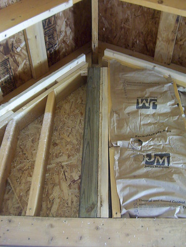
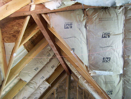
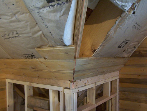
I proceeded to draw up some sketches to facilitate it. We would be changing the sheetrock ceiling in removing it and putting in decorative beams under the rafters. It seemed quite simple and made me wonder why these could not have been installed during the basic roof framing stage. After demolition of the sheetrock some insulation was installed. The frame was bolstered where the beams would sit, creating a beam saddle of sorts high over the windows.
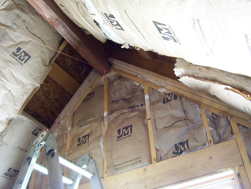
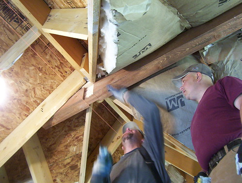
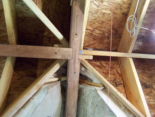
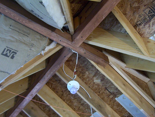
Stringline would give us approximate positioning, intersection points, and visualization if clearances needed to be removed from the rafters along it. With one extra hand we levered them up and fastened them with timberlock screws. We opted for a small housed joint at the center, then drilled it for the ceiling fan wiring and light that was previously installed.
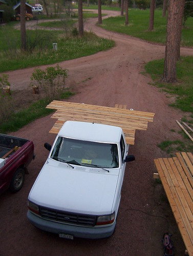
Beforehand we had hauled the beams and panelling up into the addition to condition for two weeks before staining it on a sunny day outside.
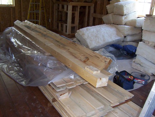
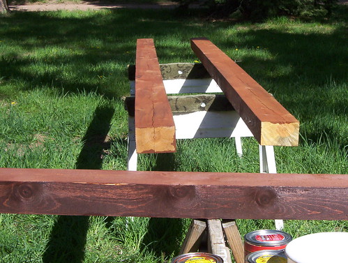
This photo above features some of the blue mineral stain of "Beetle Kill Pine" before receiving a conditioner and Puritan Pine Minwax stain.
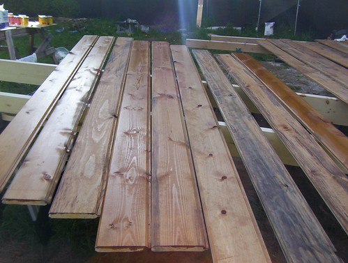
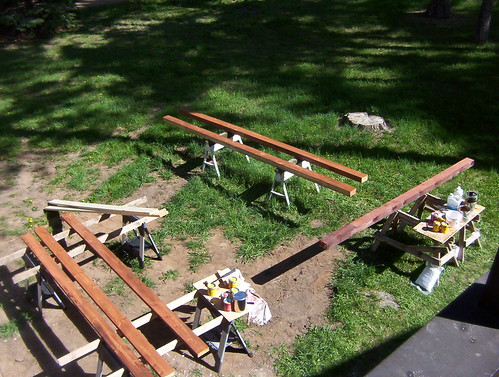
Toward the end of the day we ran out of saw horse space, the drying time slowing after the sun went over the mountain.
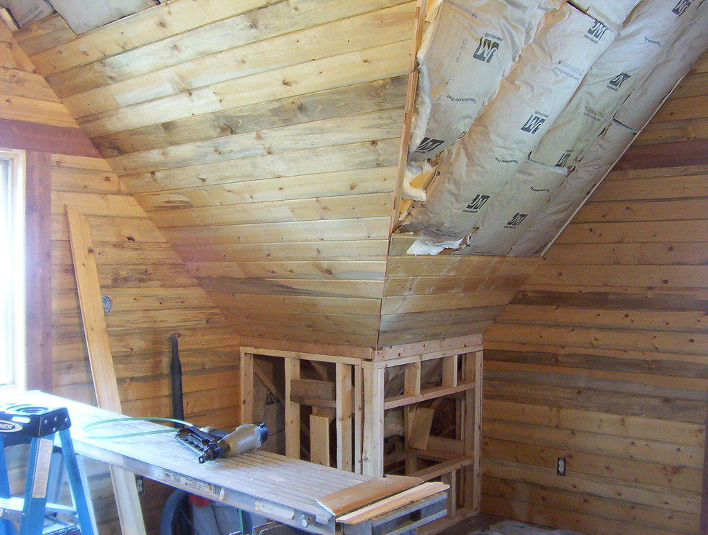
The compound angle at which the panelling edges would be cut was only half a degree off the sketch. This would be where the gables intersected each other at the valley rafter.
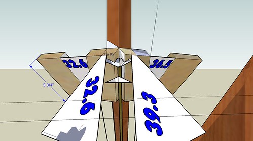
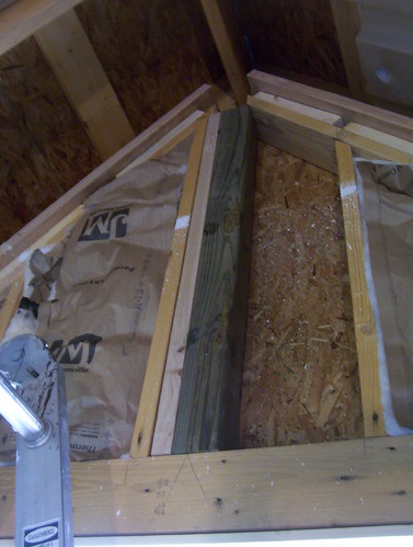
Where these gables met a deflecting curve was found on one one of the valley rafters. The stringline would again be used from the top to the knee wall to have something to follow, and to compensate for more exact lengths. A test block was also made to help find the actual fitting point or compensate for any final deviations.
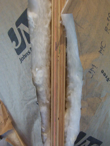
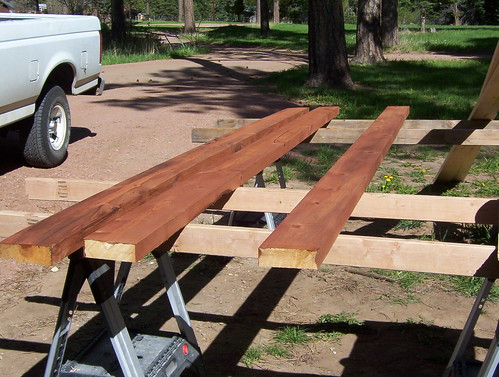
The first few boards above.
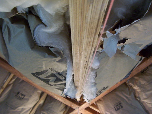
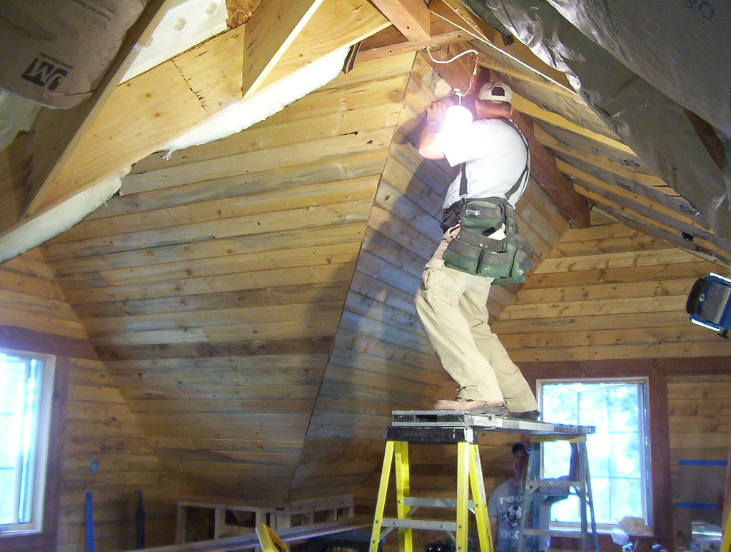
The view from the bottom upward. I took a pencil and marked a dotted line underneath the stringline. It was perhaps 3/4 of an inch at it's maximum.
The view from the top downward.
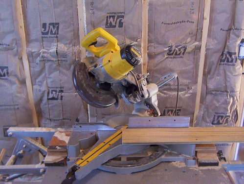
The chop saw set up. We'd have to reset positions a few times to accomodate the installation platform.
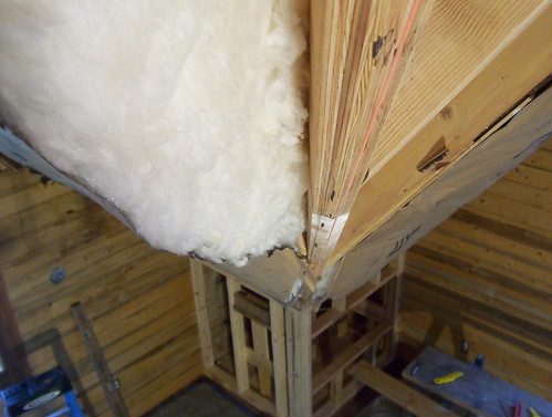
Going up one side.
Going up the other.
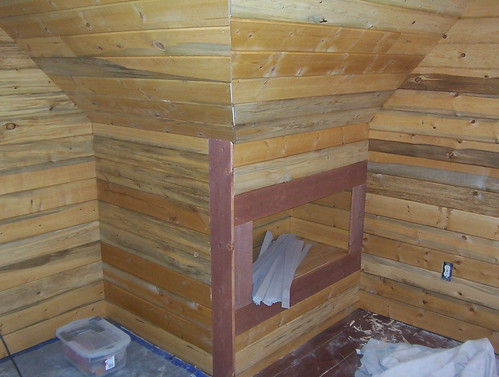
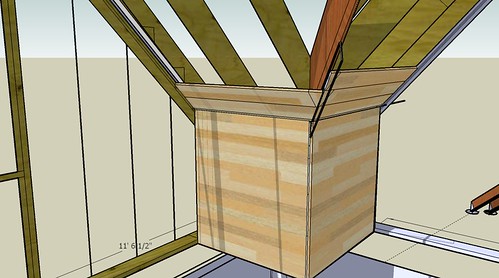
Finishing out one cubby hole. (The joint at the valley rafter will later get covered with two rough pine boards stained the beam color.)
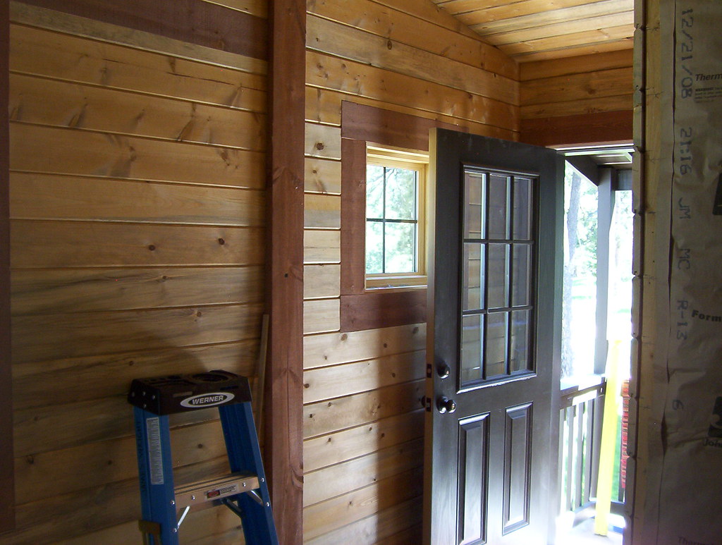
Finishing out the entryway.
No comments:
Post a Comment